|
|
| Copyright © Klaus Piontzik | ||
| German Version |
| This results in the overall circuit diagram for the ejPi measuring method, as shown in Figure 6.3.1.6.
The overall circuit diagram shown here works with any Hall sensor that has four connections and generates the analog Hall effect. If necessary, when using a different Hall sensor, i.e. different voltage properties or other operational amplifiers, adjustments may only have to be made with regard to the resistance values. If a metallic shell is attached over the Hall sensor in such a way that a Faraday cage is formed, electromagnetic influences can be excluded and it is ensured that only magnetic moments are effective. |
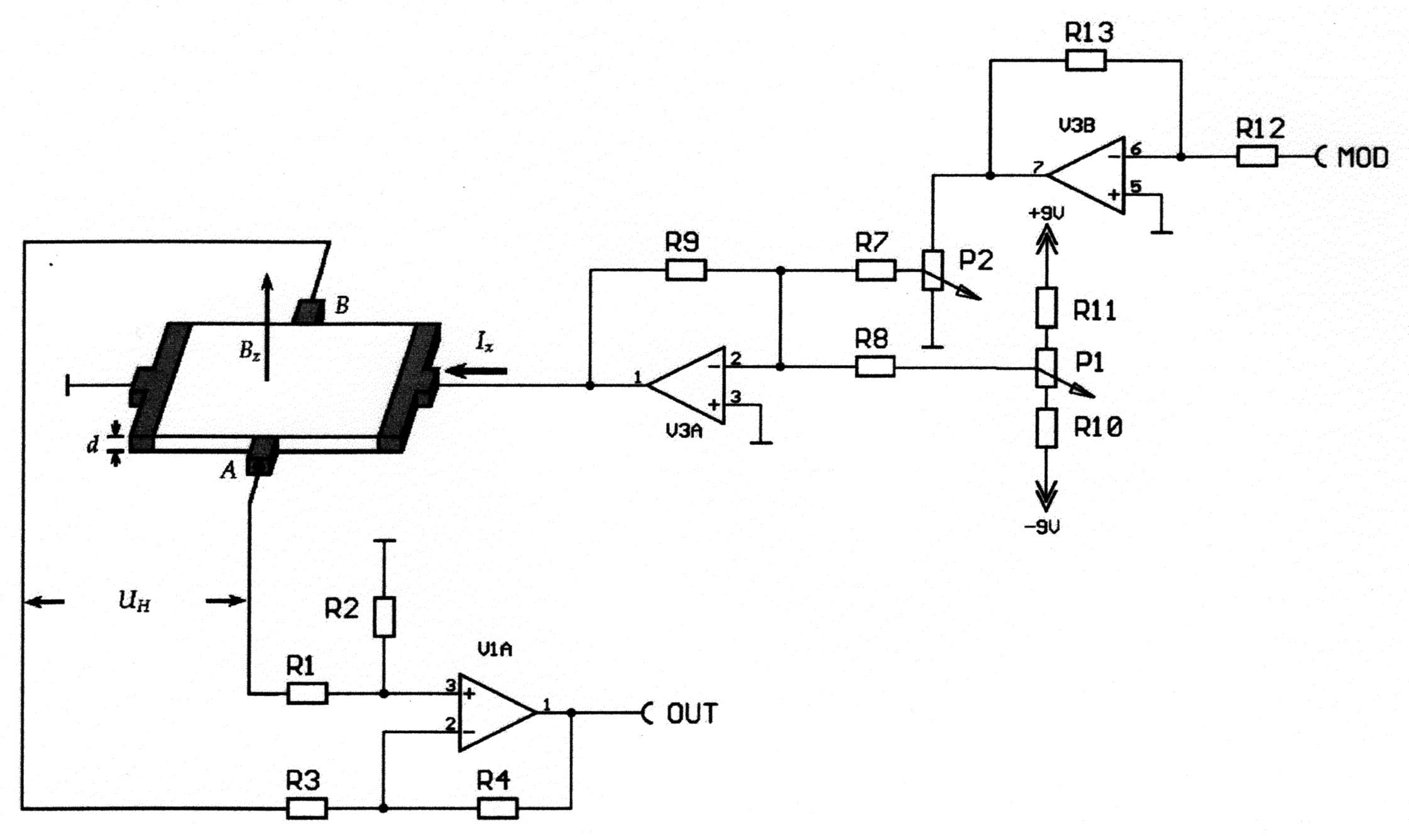 |
| Illustration 6.3.1.6 – Circuit diagram for the ejPi measuring method |
|
200 sides, 23 of them in color 154 pictures 38 tables Production und Publishing: ISBN 978-3-7357-3854-7 Price: 25 Euro |
![]()