| Copyright © Klaus Piontzik | ||
| German Version |
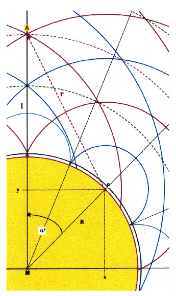
| To determine is the center distance MA=l’ of a magnetic layer. |
 |
| Illustration 2.5.2.1 – distance calculating of the magnetic layers |
| One has for the line MA: |
| and |
| There are the relations: |
| With theradius of the ball R Based on Chapter 2 each oscillation can be allocated to a certain angle a: |
| The base angle is: |  |
| n is the number
of oscillations around the circle. Alternatively, here
also the ap-plication of equation 2.05 would be possible. The distance from a starting point of the field to the next is half of the angle al-pha. Taking into account all source points, so they occur in integer multiples of half basic angle. It is so true: |
| Multiple of the angle: |  |
| In the illustration 2.5.2 one has
for the source point P: m = 2 The route of PA = r corresponds to the way the wave travels. From the source point P starting up to the oscillation layer (point A), which is to determine. Caused by the stationary state, maximum fronts and minimum fronts arises, with regular intervals spherically around the source point. After Chapter 2 corresponds a distance to half a wavelength. Hence, the way of the wave up to the oscillation layer is always an integer multiple of half a wave-length: |
| The distance travelled by the wave: |  |
| In illustration 2.5.2 applies to the wave way PA: k = 4 |
| Applies to the wavelength: |  |
| Inserting all treated terms in the equation for l’ leads to the following conclusions: |
| 2.5.2.1 - Equation: |  |
| Are alpha and Alpha line replaced by the corresponding terms from the previous considerations, so is the following layer equation: |
| 2.5.2.2 - Equation: |  |
n,m,k = 1,2,3,4,... |
| R = radius of the
sphere n = n = number of waves m = number of sources – for symmetry reasons: 1 ≤ m ≤ n k = number of half basic wavelengths to reach a layer n, m, k are integer parameters that provide by successively application, a table of layers L |
| 2.5.2.3 - Theorem: | With the radius R of the sphere all possible layers L are also given. |
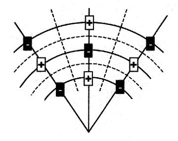
| 2.5.2.4 - Definition: This simplified view of the resulting field is apparent: |
 |
| Illustration 2.5.2.2 – grid forming |
| solid lines = extremal
lines = pole layers dashed lines = zero lines = zero walls |
| There are two viewing options: |
| 2.5.2.5 - Theorem: | The poles
form a grid-shaped radial layer system. The pole layers are stationary extremal states. If one looks at two pole layers lying on top of each other, these layers always own a counter phase order of their poles. |
| 2.5.2.6 - Theorem: | The zero walls
form a grid-shaped radial layer system. The poles are in the center of the each wrapping zero field. |

|
200 sides, 23 of them in color 154 pictures 38 tables Production und Publishing: ISBN 978-3-7357-3854-7 Price: 25 Euro |