| Copyright © Klaus Piontzik | ||
| German Version |
| In order to be able to measure magnetic fields, a physical effect
is required that reacts to magnetic flux density B. The Hall effect provides such a phenomenon. |
 |
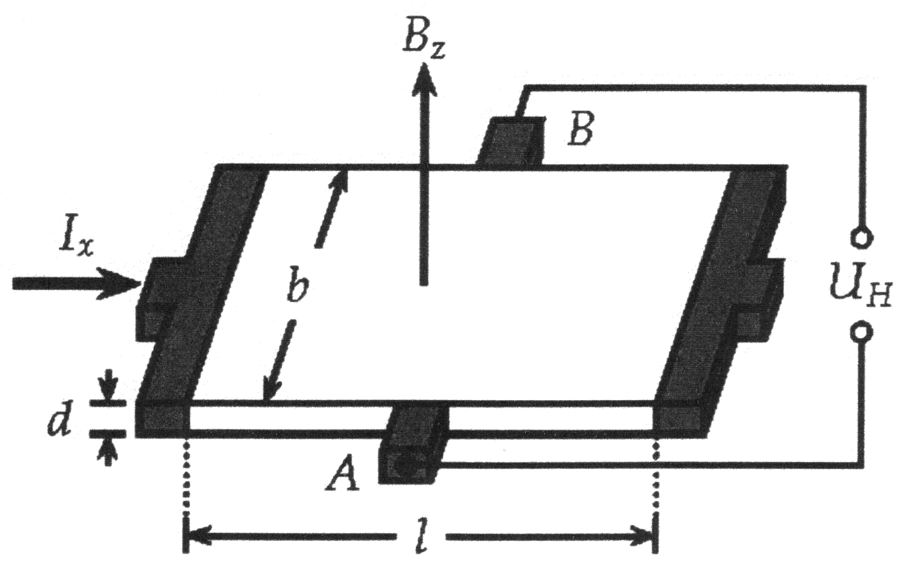
| Illustration 6.1.1 – Hall sensor |
|
As shown in Illustration 6.1.1, a very thin metal plate is flowed through
by a current Ix that is evenly distributed over its cross section. No voltage
can be detected between two points A and B, which are equidistant from the power
supply lines and which are connected to a galvanometer.
If the plate is passed through by a magnetic field B, the Lorentz force F acts on the moving charge carriers of the primary current I. This force eliminates the uniform charge distribution in the plate and leads to a potential difference UH between the two points A and B. It flows a current through a galvanometer connected to these points. The charge distribution caused by the Lorentz force creates an electric field with field strength E, which counteracts the deflection of the charge carriers. A state arises in which the Lorentz force FL and the counterforce FE caused by the electric field have the same amount. The general equation for the Hall voltage can be derived from these boundary conditions: |
| 6.1.1 Equation |
|
Where RH is the Hall coefficient and d the material thickness
of the metal plate are to be viewed as specific constants of a Hall sensor, which are summarized in a constant k Then we can generally write: |
| 6.1.2 Equation |
|
The Hall voltage only depends on the supply current IB of the sensor and the flux density B
of the acting magnetic field. The Hall sensor is operated with a direct voltage, i.e. I is constant.
In this configuration, the Hall sensor is normally used as a magnetic flux density meter. |

|
200 sides, 23 of them in color 154 pictures 38 tables Production und Publishing: ISBN 978-3-7357-3854-7 Price: 25 Euro |